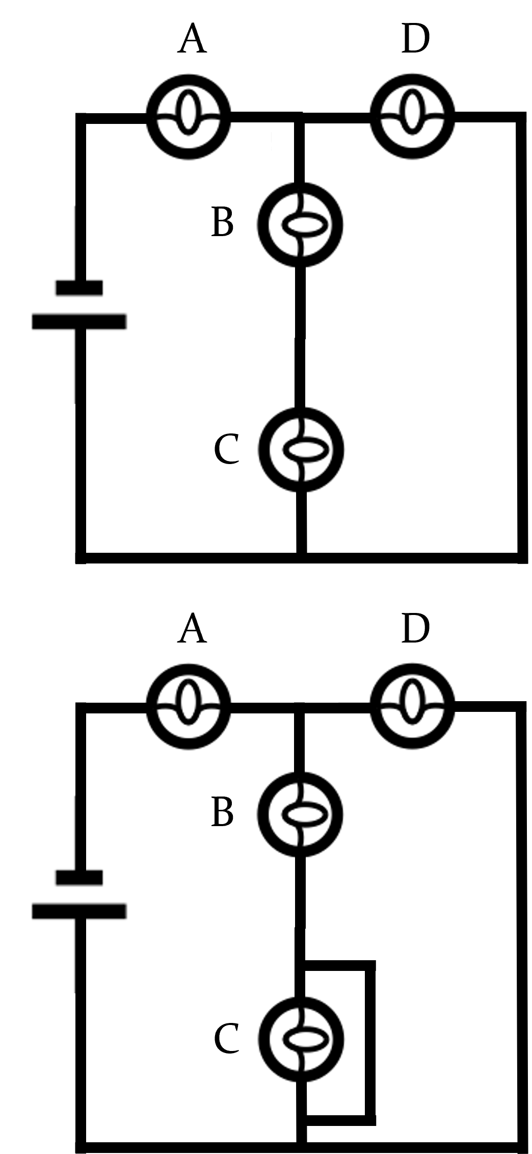
Figure26.12.1.Circuit diagram. The top and bottom circuits are identical, apart from an extra wire connecting around lightbulb C in the bottom diagram.
The quantity of charge through a conductor is modeled as \(Q(t) = (4.0 \frac{\mathrm{C}}{\mathrm{s}^4}t^4 - (1.0 \frac{\mathrm{C}}{\mathrm{s}})t + 6.0 \mathrm{mC}\text{.}\) What is the current at time t = 3.0 s?
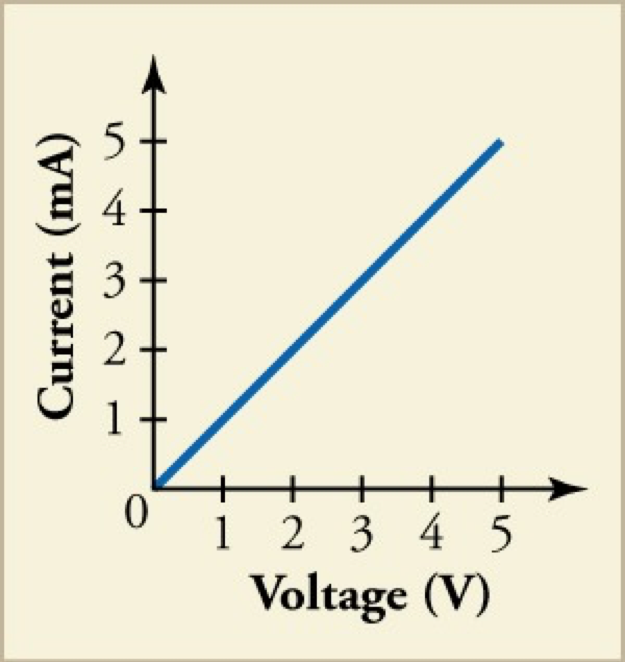
Suppose you apply several different voltage differences across a circuit and measure the resulting current through the circuit; a plot of your results is shown above. What is the resistance of the circuit?
High-voltage overhead electric lines are not covered by insulation, unlike wires that are used in electric circuitry in homes. Explain why a bird that lands on a single high-voltage line does not get electrocuted.
The bird’s feet, touching the high-voltage line, do form a complete circuit through the bird, but essentially no current flows through the bird, because the resistance value of the wire is essentially zero between the points where the bird’s feet are touching it; whereas the bird has some non-negligible resistance.
Two identical resistors are connected in parallel across the terminals of a battery. If you increase the resistance of one of the resistors, what happens to the current through, and the voltage difference across, the other resistor?
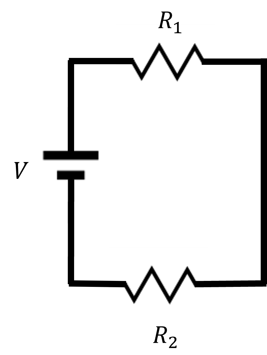
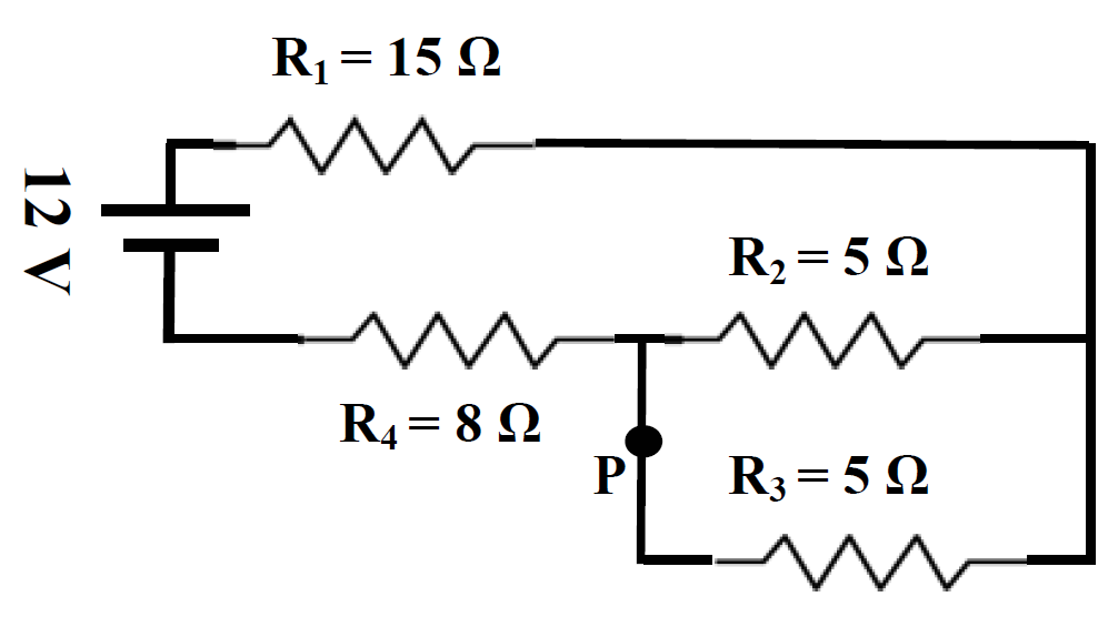
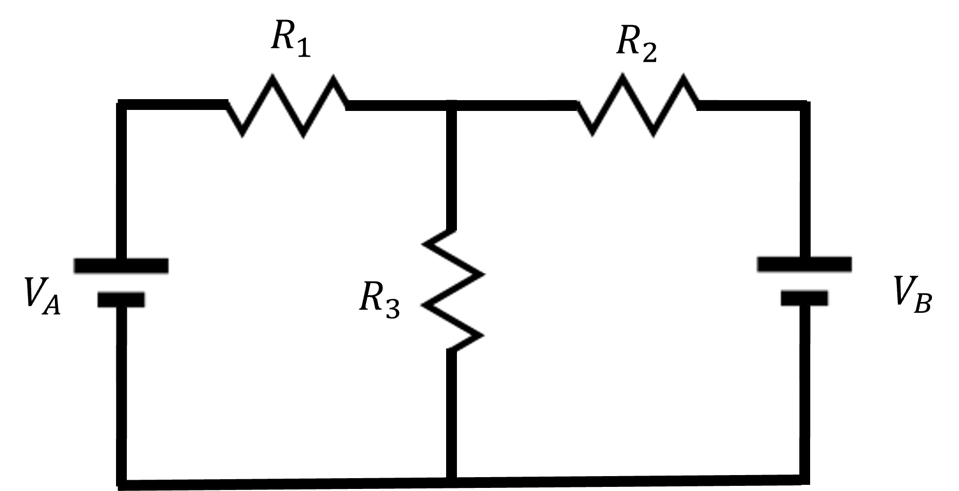
If \(V_A = 6 \ \mathrm{V}\text{,}\)\(V_B = 2 \ \mathrm{V}\text{,}\)\(R_1 = 4 \ \Omega\text{,}\)\(R_2 = 1 \ \Omega\text{,}\) and \(R_3 = 3 \ \Omega\text{,}\) find the magnitude of the current through resistor 1.
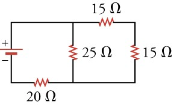
If another 5 \(\Omega\) resistor were connected in parallel with \(R_2\) and \(R_3\text{,}\) would the overall resistance of the circuit increase, decrease, or stay the same?
If another 5 \(\Omega\) resistor were connected in parallel with \(R_2\) and \(R_3\text{,}\) would the voltage difference across the battery increase, decrease, or stay the same?
If another 5 \(\Omega\) resistor were connected in parallel with \(R_2\) and \(R_3\text{,}\) would the current drawn from the battery increase, decrease, or stay the same?
If another 5 \(\Omega\) resistor were connected in parallel with \(R_2\) and \(R_3\text{,}\) would the power dissipated by \(R_4\) increase, decrease, or stay the same?
The severity of a shock depends on the magnitude of the current through your body. Would you prefer to be in series or in parallel with a resistance, such as the heating element of a toaster, if you were shocked by it? Explain.
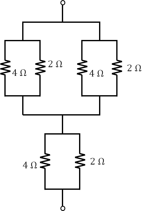
What are the largest and smallest resistances you can obtain by connecting a 36.0 \(\Omega\text{,}\) a 50.0 \(\Omega\text{,}\) and a 700 \(\Omega\) resistor together?
Practice activities provided by Ling, S. J., Moebs, W., & Sanny, J. (2016). Current and Resistance, Direct-Current Circuits. In University Physics Volume 2. OpenStax.