Section 26.4 Voltage Diagrams
In a previous section, in Voltage Sketch, you made a sketch of voltage as a function of time for a charge moving around a circuit. The video below provides a more formal representation for this idea.
Subsubsection Key Ideas
Voltage diagrams are very useful representations to draw when analyzing circuits. They can be as useful as free-body diagrams!
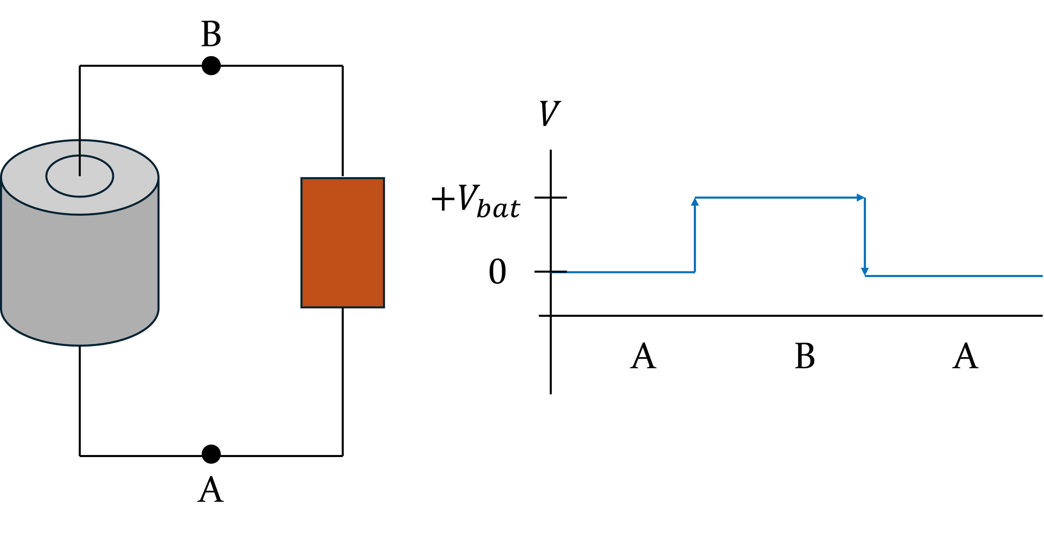
When drawing voltage diagrams, define locations between circuit elements to help guide your graph. Let’s look at the figure above to understand how a voltage diagram is drawn. In the circuit above, there are two defined points, A and B. Starting at element A moving clockwise, the voltage starts at zero, gains \(V_{bat}\) across the battery between points A and B, then loses the same amount of voltage across the orange circuit element between points B and A, returning to zero voltage at point A. The voltage diagram to the right shows this.
Typically, voltage diagrams will start at zero voltage, and are often drawn starting at the defined location just before a voltage source, like a battery, as is shown in the diagram above. It does not matter which point on the circuit you start at. For example, in the circuit above, you could start at zero voltage at point B, lose voltage between points B and A travelling clockwise, then gain voltage across the battery between points A and B, bringing you back to zero voltage when you reach point B.
Representation 26.4.3. Voltage Diagrams.
A voltage diagram shows how the voltage changes throughout a circuit. Typically, a voltage diagram starts at zero and will utilize an arrow to show how the voltage is increasing or decreasing across certain elements.The Loop Rule is often used in tandem with voltage diagrams.
