Section 25.6 Capacitors
If you have not done so already, investigate the “Capacitance” tab in the following
PhET Simulation before watching the video below.
Subsubsection Key Ideas
A capacitor is made up of two conductors separated by an insulator.
Definition 25.6.2. Capacitance.
The capacitance of a capacitor is defined as
\begin{equation*}
C = Q / \Delta V
\end{equation*}
and is dependent on the geometry of the capacitor. The units of capacitance are in farads (F).
Assumption 25.6.3. Parallel-plate Capacitor.
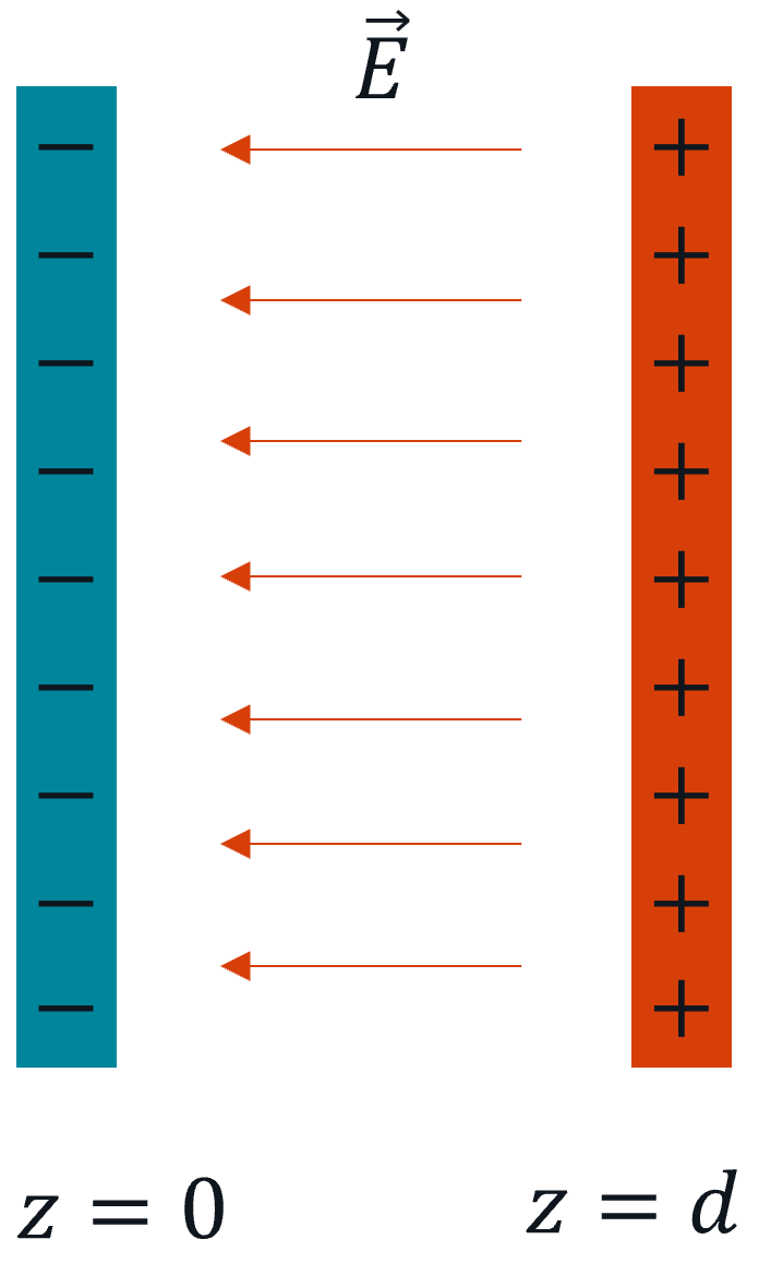
A simplified and broadly applicable model for many capacitors is to treat the conductors as two square parallel plates, shown in cross-section below, separated by a distance \(d\) that is much smaller than the width of the plates, which each have area \(A\text{.}\) Using this assumption:
-
The charge on each plate is uniformly distributed. One plate has charge \(+Q\) and the other has charge \(-Q\text{.}\)
-
The electric field between the plates is uniform, with magnitude \(E = \frac{Q}{\epsilon_0 A}\) pointing from the positive to the negative plate.
-
The capacitance depends on the geometry of the plates: \(C = \frac{\epsilon_0 A}{d}\text{.}\)