
Learning Introductory Physics with Activities

Section 18.3 Two-slit Interference

Start by playing with the light interference simulation for a few minutes. Click on the “Slits” tab and select the laser. On the right hand side, increase the number of slits to two.
Write down some observations. What happens when you move the slit width to its minimum and maximum values? What happens as you increase the slit separation? What happens when you increase and decrease the frequency?

Subsection Video Lesson: Two-slit Interference

Subsection Deriving the Interference Pattern

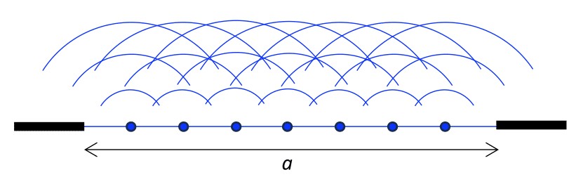
A powerful wave property allows complicated light waves to be treated as superpositions of simpler light waves. In particular, any wave front of light can be treated as a collection of point sources of spherical waves, an idea known as Huygen’s Principle.
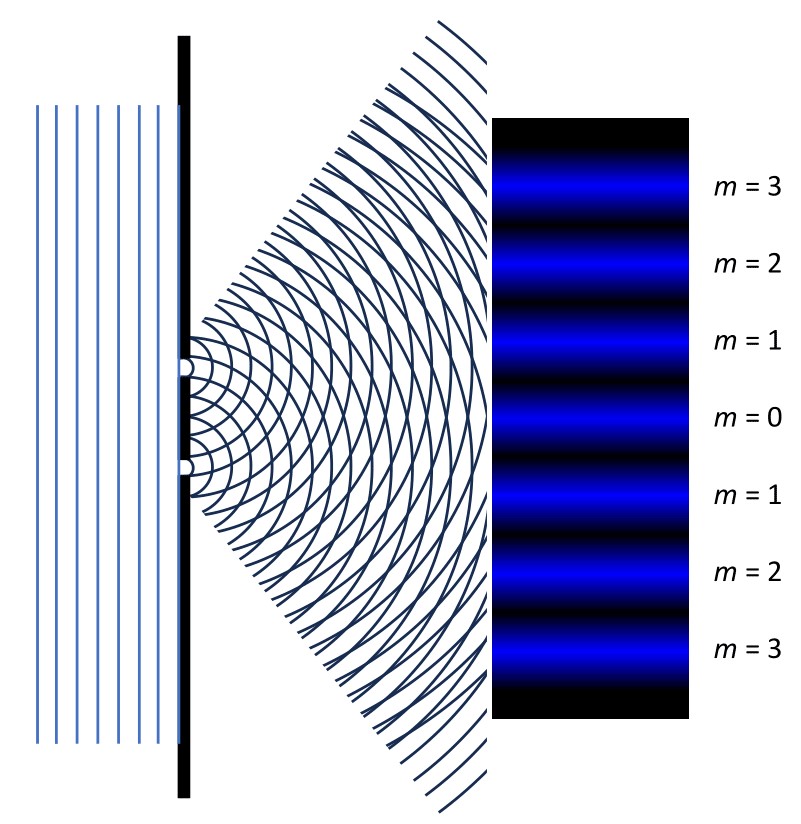
As a simple example, when a coherent beam of light is incident on two very narrow slits, as shown in the figure below, the light that emerges from the slits can be approximated as two spatially-separated point sources of coherent, in-phase spherical light waves.
A diagram showing the double-slit experiment and the interference pattern that is shown on the screen. Two slits sit on the right side. Plane waves hit the two slits from the left side. As they exist the slits, the wave front becomes spherical, and multiple concentric circles are shown to represent how the light wave behaves. The interference pattern has seven evenly distributed bright spots. The center is labelled m = 0, and the rest are labelled from m = 1 to m = 3 above and below the center.
Figure 18.3.3. Interference pattern produced by light traveling through two adjacent slits. The central maxima is at a value of \(m = 0\text{.}\)
Applying the general rules for Maximum Constructive Interference and Complete Destructive Interference from the Interference and Path Length Difference Sections allows you to determine the spacing of the interference pattern by looking at the path length difference of the rays exiting the slits. The figure below gives a magnified look at the paths traveled by the two rays.
On the left side, there is a diagram of the souble-slit experiment, with the slits sitting on the left a distance L away from a screen. A dashed line extends from the center of the slits to the screen at an angle theta sub m and hits a point y sub m on the screen on the right. A small circle covers the double-slit experiment on the right. On the right side, there is a zoomed-in picture of the double-slit set up inside a circle. Two slits sit at a distance d away from each other. A ray extends from each slit to the right side of the circle at an angle theta. The rays are labelled "r 1" and "r 2". Another line extends from the top slit to the bottom ray at an angle theta, indicating the path length difference.
Figure 18.3.4. Left: A diagram of the double slit experiment. The slits are separated from the screen by a distance of \(L\text{,}\) and the angle to the mth bright spot is denoted by \(\theta_m\text{.}\) The vertical distance to the mth bright spot is \(y_m\text{.}\) Right: A zoomed-in view of the double slits. The slits are separated by a distance \(d\text{.}\) Two different rays, \(r_1\) and \(r_2\) travel towards the screen at an angle \(\theta\text{,}\) making the path length difference between the two rays equal to \(d \sin\theta\text{.}\)
If the screen is far away from the sources, the two rays in the figure above may be treated as parallel, allowing you to calculate the path-length difference using trigonometry.
The Double-Slit Experiment was originally conducted by Thomas Young in 1801 to show that light does indeed behave like a wave. Just like water waves interacting with each other, as light travels through two slits, the crests and troughs of the light waves will interact with each other and produce an interference pattern on the screen behind the slits.

Exercises Activities

1. Constructive Interference.

Combine the geometric path-length difference found above and the general rule for Maximum Constructive Interference to find an equation relating \(d\text{,}\) \(\lambda\text{,}\) and \(\theta\) for the bright spots on the screen.
Answer.
\begin{equation*} d \sin \theta = m\lambda \end{equation*}

2. Destructive Interference.

Combine the geometric path-length difference found above and the general rule for Complete Destructive Interference to find an equation relating \(d\text{,}\) \(\lambda\text{,}\) and \(\theta\) for the dark spots on the screen.
Answer.
\begin{equation*} d \sin \theta = \left( m + \frac{1}{2} \right)\lambda \end{equation*}

3. The Small Angle Approximation.

In the video, you learned about using the Small-angle Approximation for interference. Use the small-angle approximation to write an equation relating \(d\text{,}\) \(y\text{,}\) \(L\text{,}\) and \(\lambda\) for points of maximum constructive interference.
Answer.
\begin{equation*} \sin\theta \approx \theta \approx \tan\theta = \frac{y}{L} \end{equation*}
Plugging this into the maximum constructive interference expression above gives:
\begin{equation*} d \frac{y}{L} = m\lambda \end{equation*}

4. Measure the Wavelength.

You are conducting the double slit experiment and you have a light source with an unknown wavelength. The slits are separated by a distance of \(0.5 \mathrm{~mm}\) and your screen is \(3.4 \mathrm{~m}\text{.}\) You measure the third bright fringe to be at a position of \(4.7 \mathrm{~mm}\) to the right of the center line on the screen. What is the wavelength of light?