In most cases, we will assume that the thickness of the lens is much smaller than the radii of curvature of the sides of the lens. This simplifies our ray diagrams and calculations because it allows us to treat the light ray as bending within the optical plane of the lens.
The Thin-Lens Equation is defined as \(\frac{1}{d_o} + \frac{1}{d_i} = \frac{1}{f}\text{,}\) where \(d_o\) is the object distance to the lens, \(d_i\) is the image distance to the lens, and \(f\) is the focal length. The image distance is positive for real images and negative for virtual images. This equation is only valid when using the Thin-Lens Approximation.
Additional Detail11.8.4.Derive the Thin-Lens Approximation Equation.
You saw in the previous video the equation for a thin-lens (Thin-Lens Equation). Derive this equation. It will be helpful to start with a ray diagram of an object in front of a lens producing an image. There are a couple different ways to derive this, so be creative!
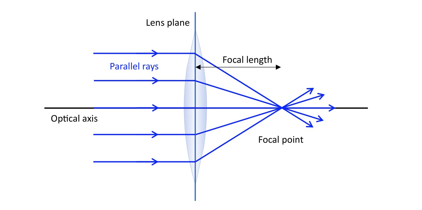
When light passes through the converging lens, all parallel rays converge to the focal point of the lens. If the object is located past the focal length of the lens, as light enters the lens from one side, the light is bent, or converges, to a single point on the opposite side, producing a real image. If the object is located within the focal length of the lens, the image produced is virtual.
Figure11.8.7.A converging lens. Under the thin-lens approximation, light rays that are parallel to the optical axis will refract at the lens plane, and converge to the focal point.
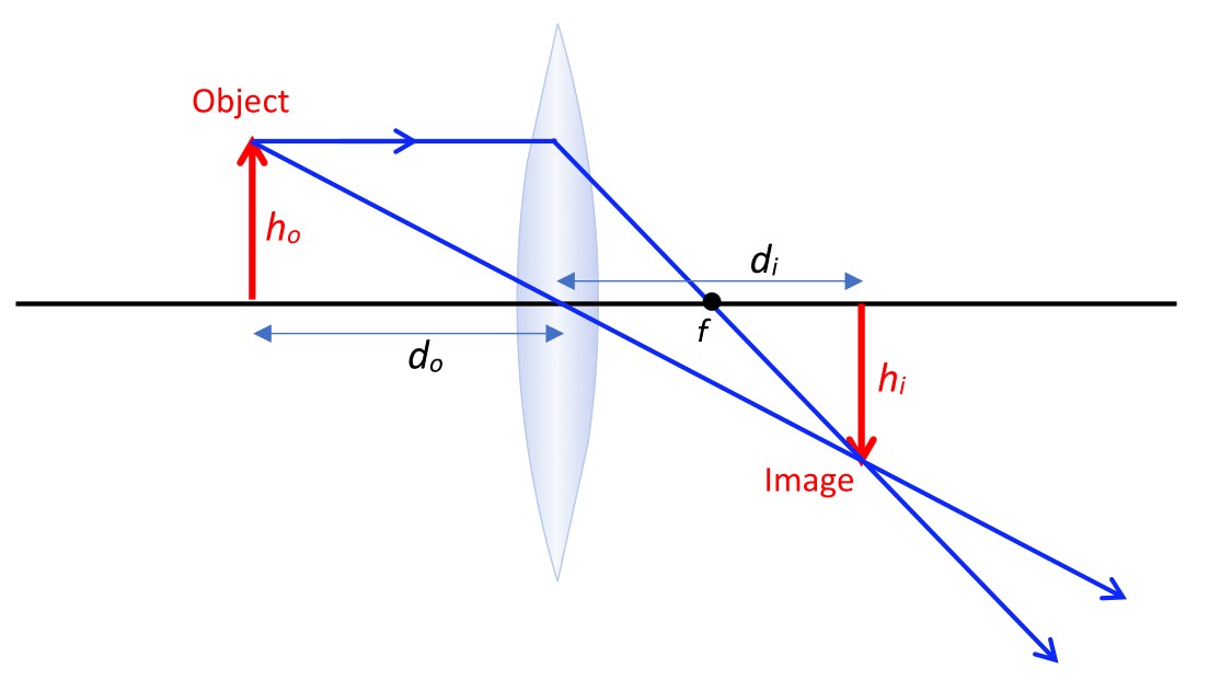
Figure11.8.8.A converging lens producing an image. An object of height \(h_o\) sits at a distance \(d_o\) from the lens. The image is located at a distance \(d_i\) from the lens on the opposite side, and has a height \(h_i\text{.}\)
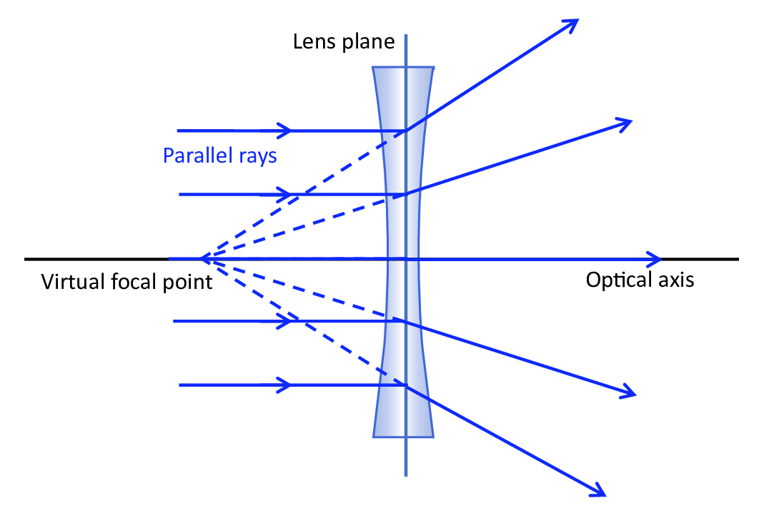
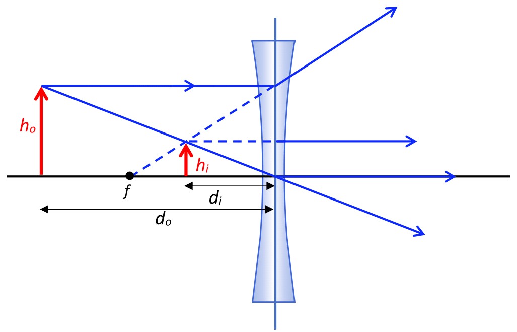
Light rays will diverge away from each other after they exit a diverging lens. These lenses have two curved surfaces inwards. These types of lenses always produce a virtual image located within the virtual focal length of the lens.
Figure11.8.11.A diverging lens. Under the thin-lens approximation, light rays that are parallel to the optical axis will refract at the lens plane, and diverge away from each other on the opposite side of the lens, while a virtual image is created at the virtual focal point.
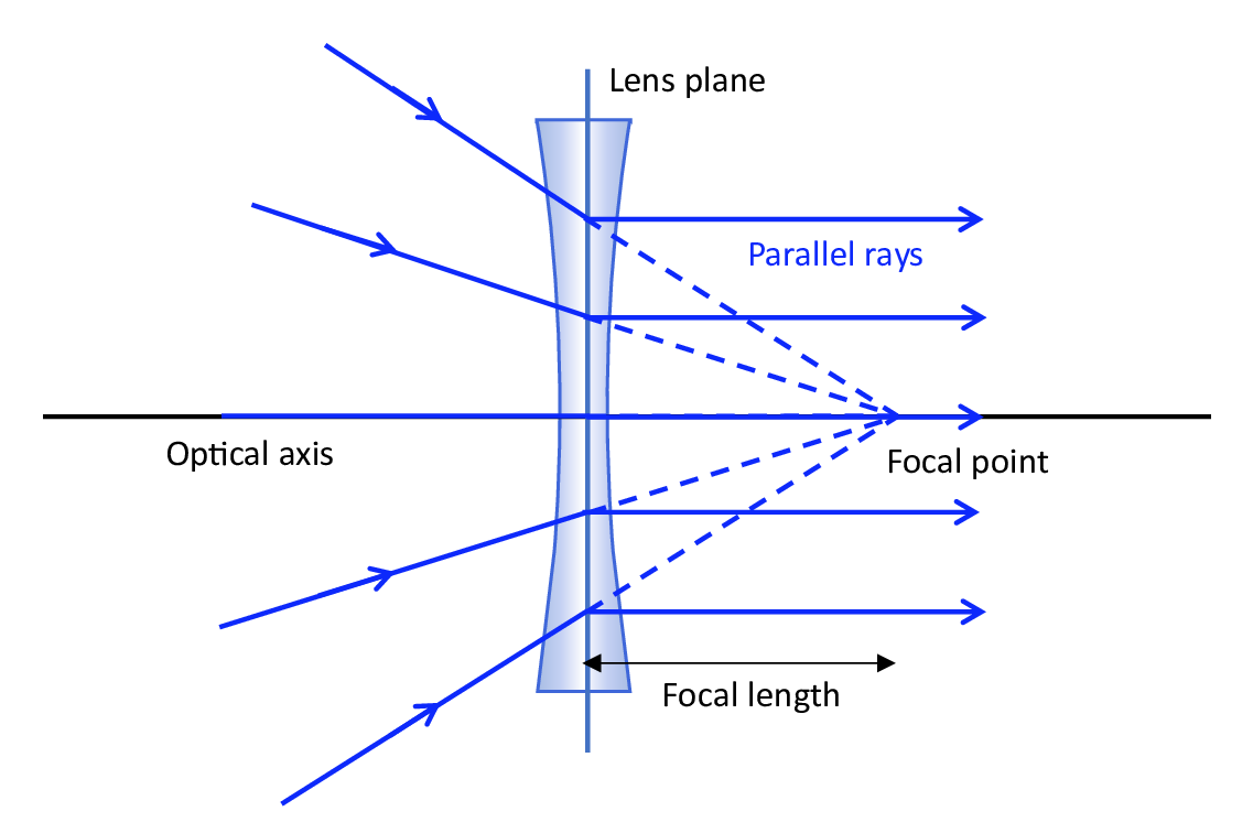
Figure11.8.12.A diverging lens. Under the thin-lens approximation, converging light rays will enter the lens, refract at the lens plane, and will exit the lens parallel to the optical axis.
Figure11.8.13.A diverging lens producing an image. An object of height \(h_o\) sits at a distance \(d_o\) from the lens. The virtual image is located at a disatnce \(d_i\) from the lens on the same side as the object, and has a height \(h_i\text{.}\)
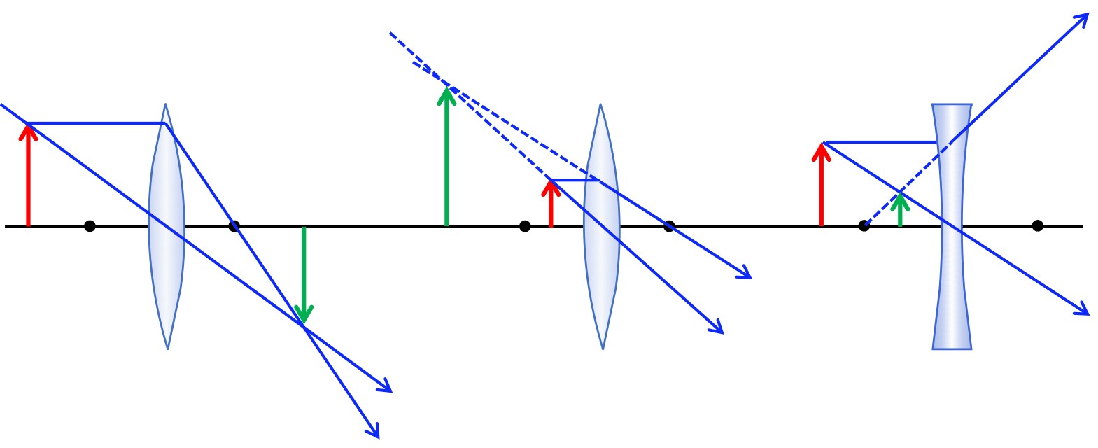
Summarize what you have learned about lenses. Use the following figure in your explanation. Explain each part of the diagram, whether it is a converging or diverging lens, and what type of image is produced and why. Can you come up with a set of rules to follow that will help you draw ray diagrams for lenses?